


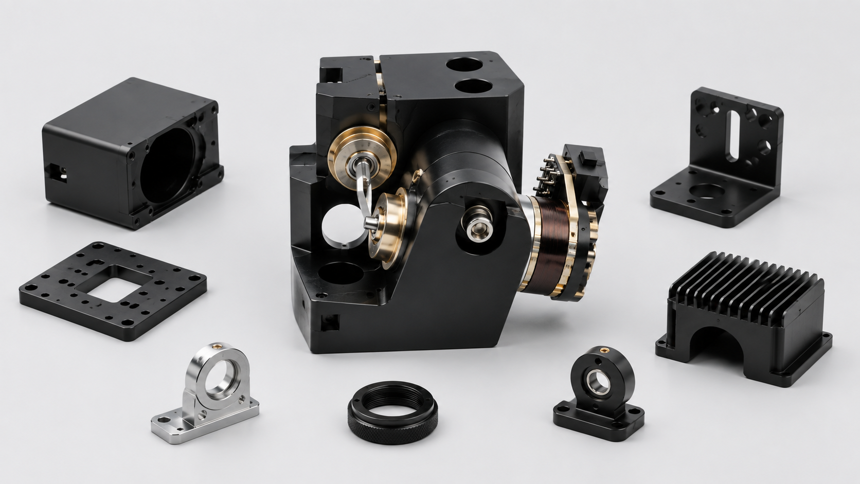
A precision optical housing is rarely difficult because of one tight dimension. The real challenge is keeping the lens bore, sensor surface, mounting holes, and optical interfaces in the correct relationship after machining, anodizing, and inspection.
At XY-GLOBAL, we manufacture optomechanical components for optical, semiconductor, imaging, laser, medical, and sensing equipment. Our work focuses on precision CNC parts with complex geometry, tight GD&T, and critical alignment features.
What Optomechanical Components Can We Manufacture?
Typical optomechanical components we support include:
-
Lens barrels and optical tubes
-
Camera and detector housings
-
Optical and laser mounts
-
Sensor bases and brackets
-
Alignment plates
-
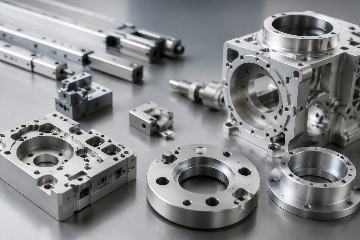
Precision aluminum housings
-
Multi-face optical structures
Common materials include 6061, 7075, stainless steel, titanium, and engineering plastics.
Our CNC machining capability can support tolerances down to approximately 0.005 mm, depending on material, geometry, feature size, and part structure.

Tight Tolerances Are Only Part of the Job
For optical hardware, a ±0.01 mm dimension does not tell the whole story.
The drawing may also require tight control of:
-
Position
-
Flatness
-
Parallelism
-
Perpendicularity
-
Runout
-
Bore alignment
-
Surface roughness
For example, a lens bore can meet its diameter tolerance but still cause an assembly problem if its axis is not properly related to the mounting surface.
That is why we review the functional datum structure and critical GD&T, rather than simply checking individual dimensions.
For complex optomechanical components, this becomes especially important when several optical and mechanical interfaces must align within the same part.
5-Axis Machining for Complex Optical Parts
Consider a housing containing a central precision bore, an angled optical interface, side mounting holes, and a sensor mounting surface.
A conventional process may require several fixtures. Each time the part is repositioned, the critical relationship between features must be re-established.
With 4-axis or 5-axis CNC machining, more features can often be completed from one controlled setup.
This is particularly useful for:
-
Angled optical mounts
-
Multi-face housings
-
Complex sensor brackets
-
Laser structures
-
Parts with critical features on several orientations
For these optomechanical components, the advantage of 5-axis machining is not simply the ability to produce complex shapes — it is reducing unnecessary setup changes while keeping critical features related to the same machining reference.

Lens Barrels and Mill-Turn Machining
Lens barrels often combine precision turned geometry with milled features.
Turning is used for the lens seats, bores, shoulders, grooves, and threads, while milling may be required for radial holes, flats, slots, mounting ears, or connector features.
Mill-turn machining allows these features to be produced in a more integrated process.
Thin-wall barrels require additional attention. Removing large amounts of material or applying excessive clamping force can affect roundness and dimensional stability. Thin walls are known to be more susceptible to deflection and warping during machining.
For this reason, machining sequence, fixture force, roughing allowance, and final finishing strategy must be considered before production.
Black Anodizing and Precision Features
Black anodizing is common on aluminum optomechanical components, particularly housings located near optical paths.
But the important question is not simply whether the part can be anodized.
We first check:
-
Which bores are precision fits?
-
Which surfaces require masking?
-
Are threads allowed to be coated?
-
Which surfaces affect optical alignment?
-
Should final dimensions be verified after finishing?
This prevents a surface-treatment requirement from becoming an assembly problem later.
For optical housings where stray light matters, surface texture and internal geometry — such as grooves, recesses, or baffles — may also need to be considered instead of relying only on a black finish.
A Typical Manufacturing Challenge
A common RFQ may look straightforward: a black-anodized aluminum housing with several pockets, a precision mounting surface, bores on different faces, and tight positional requirements.
The drawing is machinable.
The real question is how to machine it without losing the relationship between those features.
Our engineering review normally focuses on three things:
1. Critical datums
Which surfaces or axes determine the optical and assembly position?
2. Machining sequence
Can critical features be completed in the same setup, and which surfaces should be finished last?
3. Final inspection
Should the feature be checked before or after surface treatment, and which GD&T characteristics need CMM verification?
This is the type of DFM review that can prevent problems before the first parts are made.

Inspection of Optomechanical Components
XY-GLOBAL uses dimensional inspection equipment including CMM for precision components, with CMM measurement resolution down to approximately 0.001 mm.
Depending on the drawing, inspection can cover:
-
Position
-
Flatness
-
Parallelism
-
Perpendicularity
-
Profile
-
Bore dimensions
-
Runout
-
Surface roughness
For prototype and NPI projects, dimensional reports can also be provided for drawing-critical characteristics.
From Prototype to Production
Many optomechanical components begin with only a small prototype batch.
The first parts are often used to confirm assembly fit, alignment, surface treatment, and critical dimensions before the process is released for repeat production.
XY-GLOBAL supports CNC milling, CNC turning, mill-turn machining, multi-axis machining, surface finishing, inspection, and assembly support.
If you are sourcing custom optomechanical components, send us your 2D drawing, 3D CAD file, material, quantity, surface finish, and critical tolerances. We can review the manufacturing risks and provide DFM feedback with the quotation.

分享:
Alloy Steel Investment Casting: A Practical Guide for Complex, High-Strength Parts
Micromachining Services For Medical Device Components