


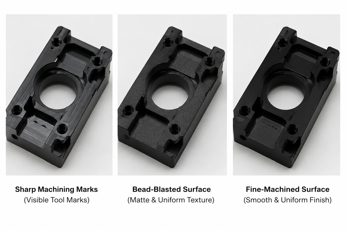
Black anodized aluminum is widely used for CNC machined housings, brackets, optical mounts, electronic enclosures, robotics components and other precision parts. The finish provides corrosion protection, improves surface durability and creates a clean black appearance without covering fine machined features with a thick layer of paint.
For precision CNC parts, however, black anodizing should not be treated as a cosmetic process added after machining.
The anodizing type, coating thickness, aluminum alloy, surface preparation and masking requirements can all affect the final dimensions, threads, bearing fits and appearance of a part.
A drawing that simply says “Black Anodize” may therefore leave several important engineering questions unanswered.
This guide explains how to specify black anodizing correctly and how to prevent common problems before production.

What Is Black Anodized Aluminum?
Anodizing is an electrochemical process that converts the aluminum surface into an aluminum oxide layer.
Unlike paint or powder coating, the anodic layer is formed from the aluminum surface itself. The porous oxide layer can then absorb black dye before being sealed.
For CNC machined components, black anodizing is commonly selected when a part requires a combination of:
-
corrosion resistance
-
surface durability
-
black cosmetic appearance
-
relatively thin surface treatment
-
electrical insulation
-
controlled dimensional change
It is commonly applied to aluminum housings, mounting plates, optical components, robotics parts, instrument structures and electronics hardware.
However, the result depends heavily on the anodizing type and aluminum alloy.
Type II vs Type III Black Anodizing
Type II and Type III anodizing are not simply two different levels of the same cosmetic finish.
They are normally selected for different engineering reasons.
| Item | Type II Anodizing | Type III Hard Anodizing |
|---|---|---|
| Main purpose | Corrosion protection and cosmetic finish | Wear and abrasion resistance |
| Typical appearance | Uniform dyed black possible | Grey, dark grey, brown-black or black |
| Coating | Relatively thin | Significantly thicker |
| Dimensional effect | Moderate | Much more important |
| Cosmetic consistency | Generally better | More alloy and thickness dependent |
| Typical parts | Housings, covers, brackets, optical mounts | Sliding parts, wear surfaces, mechanical components |
Type II Black Anodizing
Type II sulfuric acid anodizing is usually the better choice when appearance, corrosion resistance and moderate surface protection are the main requirements.
It is widely used for black anodized CNC parts such as:
-
optical housings
-
camera and sensor components
-
electronic enclosures
-
brackets
-
instrument panels
-
robotics structures
When a drawing calls for MIL-PRF-8625 Type II, Class 2, Black, Class 2 indicates a dyed coating.
For cosmetic black aluminum parts, Type II usually gives more predictable results than a thick hard anodized coating.
Type III Hard Anodizing
Type III is primarily a functional coating.
It is selected where wear resistance, abrasion resistance or increased surface durability is more important than obtaining a perfectly uniform cosmetic black.
The coating is substantially thicker than normal Type II anodizing. Under MIL-PRF-8625, the nominal Type III coating thickness is 0.002 inch, approximately 50.8 μm, unless another thickness is specified.
This thickness has a direct effect on precision dimensions.
Type III should therefore not be specified simply because it sounds “better” or “stronger.”
For a stationary aluminum enclosure that only needs a black cosmetic finish, Type II may be the more appropriate and economical choice.

How Thick Is Black Anodizing?
There is no single correct black anodizing thickness.
Thickness should be selected according to the required corrosion resistance, wear performance, appearance and dimensional tolerance.
For many commercial Type II applications, coatings are commonly produced in the approximate 5–25 μm range depending on the specification and process.
Type III hard anodizing is normally much thicker and may be specified around 25–50 μm or more depending on the functional requirement.
The important point for designers is not to assume that “black anodized” automatically defines the coating thickness.
If dimensions are critical, the drawing should state the required anodizing specification and thickness.
For example:
ANODIZE PER MIL-PRF-8625, TYPE II, CLASS 2, BLACK
If a specific coating thickness is required, it should also be defined on the drawing.
How Anodizing Changes CNC Part Dimensions
This is one of the most important design considerations for black anodized CNC parts.
The anodic coating does not grow entirely inward or entirely outward.
Part of the oxide penetrates into the original aluminum surface and part grows above the original surface.
For engineering estimation, approximately half of the coating thickness may contribute to outward surface growth, although the actual result depends on the alloy and anodizing process.
Consider a simplified example.
A precision bore is machined to:
Ø10.000 mm
The specified anodizing coating thickness is:
50 μm
If approximately half of the oxide thickness grows outward from each bore surface, each wall may reduce the bore radius by approximately:
25 μm
Because there are two sides of the bore:
25 μm + 25 μm = 50 μm
The finished bore could therefore approach:
Ø9.950 mm
This is already enough to cause a serious problem for a bearing seat or precision sliding fit.
The same principle applies in the opposite direction to external diameters.
This is why dimensions such as bearing bores, shafts, locating diameters and precision slots should be reviewed before anodizing.
Do not simply machine every feature to its final drawing dimension and then add a thick anodic coating afterward.

Threads Need Special Attention Before Black Anodizing
Threaded holes are another common source of problems.
Anodizing changes both the thread surface and effective fit. On small or tight threads, even a relatively thin coating can affect assembly.
Depending on the function of the thread, several strategies may be considered:
| Method | When It May Be Used |
|---|---|
| Anodize the thread normally | Non-critical threads with sufficient clearance |
| Mask the thread | Tight threads or areas that must remain conductive |
| Compensate before anodizing | When controlled finished thread fit is required |
| Re-tap after anodizing | Possible in some applications, but removes coating from the thread |
There is no universal answer.
The correct method depends on thread size, tolerance class, corrosion requirement, electrical requirement and assembly function.
For critical threaded features, the required condition should be shown on the drawing rather than left for the anodizing supplier to decide.
Should Bearing Bores and Press-Fit Areas Be Anodized?
Not always.
A bearing bore, dowel hole or press-fit diameter may have only a few microns of usable tolerance.
Adding an anodic layer can turn a correct machined dimension into an interference problem.
Three common approaches are:
1. Pre-compensate the machining dimension
Machine the feature slightly larger or smaller so that it reaches the required size after anodizing.
2. Mask the precision feature
Prevent anodizing from forming on the functional surface.
3. Finish-machine the feature after anodizing
This can achieve the final dimension but removes the anodic layer from the machined area.
The correct approach depends on whether dimensional accuracy, corrosion protection, wear resistance or electrical insulation has priority.
This decision should ideally be made during DFM review rather than after the finished parts fail assembly.
6061 vs 7075 for Black Anodizing
Material selection has a noticeable effect on anodizing appearance.
6061-T6
6061 is one of the most practical aluminum alloys for CNC machining followed by black anodizing.
It offers:
-
good machinability
-
good mechanical strength
-
reliable anodizing behavior
-
relatively consistent dyed appearance
-
wide material availability
For housings, brackets, optical components and other cosmetic CNC parts, 6061-T6 is often a good balance between mechanical performance, cost and anodizing quality.
7075-T6
7075 provides significantly higher strength than 6061, making it useful for highly loaded structural components.
However, its zinc and copper content influences the anodizing response.
Compared with 6061, black anodized 7075 may appear:
-
darker
-
grey-black
-
slightly brown or bronze
-
less visually consistent between batches
This does not necessarily mean that the anodizing process is defective.
It can be a consequence of the alloy chemistry.
If two neighboring components must visually match, using 6061 for one part and 7075 for another can create unnecessary cosmetic risk.
For assemblies where color consistency is important, using the same alloy and preferably the same material batch makes the finishing process easier to control.

What About Cast Aluminum?
Cast aluminum can be anodized, but achieving the same cosmetic result as machined 6061 is more difficult.
Many casting alloys contain relatively high levels of silicon.
The silicon affects how the anodic layer forms and can produce a surface that looks:
-
grey
-
cloudy
-
mottled
-
less uniform
-
less deeply black
This is especially relevant when comparing a CNC-machined 6061 cover with an A380 or other die-cast aluminum body.
Even if both drawings specify “black anodized,” the two components may not visually match.
If a die-cast component requires a very consistent decorative black surface, alternative finishes such as powder coating or painting may sometimes be more suitable.
The correct decision depends on the functional requirement.
Bead Blasting Before Black Anodizing
The appearance of a black anodized CNC part is determined before it enters the anodizing bath.
Machining marks, scratches, tool paths and local polishing differences may still be visible after anodizing.
Bead blasting is often used before black anodizing to create a more uniform matte appearance.
A typical process sequence may be:
CNC machining → deburring → bead blasting → cleaning → anodizing → dyeing → sealing → inspection
Bead blasting can help reduce visible machining direction and produce a consistent matte finish, but it is not a repair process.
Deep scratches, dents and machining defects cannot simply be hidden with anodizing.
Blasting conditions should also be controlled because different media, pressure and exposure times can change surface texture.
For cosmetic assemblies, the surface preparation method should remain consistent from batch to batch.
Why Two Black Anodized Parts Can Look Different
“Black” is not a precise engineering color specification by itself.
Several factors can change the final shade:
-
aluminum alloy
-
material lot
-
coating thickness
-
machining surface condition
-
bead blasting
-
dye concentration
-
processing time
-
sealing
-
surface orientation
-
lighting conditions
A black anodized 6061 housing may therefore not look identical to a black anodized 7075 bracket.
Even parts made from the same nominal alloy can show slight batch-to-batch differences.
If cosmetic appearance is important, it is better to define:
-
same material grade
-
consistent surface preparation
-
acceptable master sample
-
cosmetic surfaces
-
allowed rack-mark locations
-
acceptable color variation
For highly appearance-sensitive products, relying only on the words “black anodized” is not enough.
How to Specify Black Anodizing on a Drawing
A useful drawing callout should communicate more than color.
A common example is:
ANODIZE PER MIL-PRF-8625, TYPE II, CLASS 2, BLACK
For tighter engineering control, additional information may include:
-
required coating thickness
-
surfaces to be masked
-
cosmetic surfaces
-
electrical contact areas
-
threads that must remain untreated
-
bearing or press-fit surfaces
-
acceptable rack locations
-
sealing requirements
-
post-anodizing dimensions
-
inspection requirements
For example:
ANODIZE PER MIL-PRF-8625, TYPE II, CLASS 2, BLACK. MASK BEARING BORE AND ALL THREADED HOLES.
The exact callout should always match the customer's applicable specification and product requirements.
A manufacturing supplier should not guess which functional surfaces may be coated.
A Practical Tolerance Example
Consider an aluminum optical housing with these requirements:
-
Material: 6061-T6
-
Finish: matte black anodized
-
Precision bore: Ø20.000 +0.010 / 0 mm
-
Internal M3 threads
-
Visible exterior surfaces
The bore has only 0.010 mm total dimensional tolerance.
Allowing the anodic coating to build freely on that bore could consume the entire tolerance.
A practical DFM review should therefore identify the bore before production and determine whether it should be:
-
masked,
-
machined with coating compensation, or
-
finished after anodizing.
The M3 threads should also be reviewed because small internal threads can become tight after finishing.
Meanwhile, the visible external surfaces may benefit from controlled bead blasting before black anodizing to produce a consistent matte appearance.
This is a better approach than treating all surfaces of the component in exactly the same way.
Black Anodizing for Optical Components
Black anodized aluminum is common in optical housings, lens mounts, sensor brackets, camera components and laser equipment.
The black finish provides a clean appearance and can reduce visible glare compared with bare machined aluminum.
However, standard black anodizing should not automatically be considered a precision optical black coating.
If stray-light control or reflectance is a critical optical requirement, surface reflectance should be specified and tested rather than judged only by visual color.
This distinction matters in imaging, laser and measurement systems.
For optical mechanical parts, dimensional control is often equally important.
Lens bores, locating shoulders, fine threads and alignment datums may need to remain within tight tolerance after anodizing.
Surface finishing and machining should therefore be planned together.
Inspection of Black Anodized CNC Parts
Inspection should not stop when machining is completed.
Critical dimensions should be verified in the condition specified by the drawing, particularly when the tolerance applies after finishing.
Depending on the component, inspection may include:
| Inspection Item | Purpose |
|---|---|
| CMM or dimensional inspection | Verify post-finish critical dimensions |
| GO/NO-GO thread gauges | Check thread usability after anodizing |
| Coating thickness measurement | Confirm specified anodizing thickness |
| Visual inspection | Check scratches, stains and color consistency |
| Masking inspection | Confirm protected areas are correctly located |
| Assembly test | Verify bearings, shafts or mating parts fit correctly |
| Surface roughness inspection | Verify functional or cosmetic texture when specified |
For precision parts, inspection drawings should clearly identify which dimensions apply before finishing and which apply to the finished component.
This prevents disputes between machining dimensions and final assembly dimensions.
Common Black Anodizing Problems
Most anodizing problems are easier to prevent during design and machining than to correct afterward.
Bore Becomes Too Small
Cause: coating growth was not included in the tolerance calculation.
Solution: compensate the machining dimension, mask the bore or define a post-finishing operation.
Thread Does Not Assemble Smoothly
Cause: anodizing changes the effective thread fit.
Solution: evaluate masking or machining compensation before production.
Black Parts Do Not Match
Cause: different alloys, material batches, surface preparation or anodizing conditions.
Solution: standardize alloy, preparation and batch processing where cosmetic matching is important.
Rack Marks Appear on Visible Areas
Cause: anodizing requires electrical contact with the component.
Solution: define acceptable rack locations on non-cosmetic surfaces.
Surface Looks Patchy After Anodizing
Cause: machining marks, scratches, alloy variation or inconsistent pretreatment may remain visible.
Solution: control the incoming machined surface and surface preparation before anodizing.
Black Anodizing Should Be Considered Before CNC Machining
The most important point is simple:
Do not wait until machining is complete to think about anodizing.
For precision black anodized aluminum parts, machining and surface treatment are part of the same manufacturing process.
Before production, review:
-
alloy selection
-
anodizing type
-
coating thickness
-
final dimensional tolerance
-
bearing and press-fit surfaces
-
threaded holes
-
masking areas
-
electrical contact surfaces
-
cosmetic requirements
-
inspection condition
This is especially important for optical equipment, medical device structures, robotics, semiconductor equipment and precision instruments where a small dimensional change can affect final assembly.
Black Anodized Aluminum Parts From XY-GLOBAL
XY-GLOBAL manufactures custom aluminum CNC components from prototype through production, with support for machining, surface finishing and dimensional inspection.
For black anodized aluminum parts, our engineering review focuses not only on whether a component can be machined, but also on what happens after surface treatment.
Critical bores, threads, datum surfaces, press fits, masking areas and cosmetic surfaces can be reviewed before production so that machining dimensions and anodizing requirements work together.
Typical components include:
-
precision aluminum housings
-
optical mounts and lens barrels
-
sensor and camera components
-
electronics enclosures
-
robotics components
-
medical equipment structures
-
automation equipment parts
If you have a black anodized aluminum CNC project, send the 2D drawing and 3D model together with the material, anodizing specification, quantity and cosmetic requirements.
Early DFM review can identify finishing risks before they become assembly problems.

FAQ
Does black anodizing change aluminum dimensions?
Yes. The anodic oxide layer changes the final surface dimension. This is particularly important for Type III hard anodizing, bearing bores, precision diameters, threads and press-fit features.
Is 6061 or 7075 better for black anodizing?
6061 is generally easier to control when a uniform cosmetic black finish is important. 7075 can also be anodized successfully, but its alloy composition may produce a darker or less uniform appearance. If strength is the priority, 7075 may still be the correct choice.
What is the difference between Type II and Type III black anodizing?
Type II is commonly used for corrosion protection and decorative dyed finishes. Type III produces a thicker hard anodic coating and is selected mainly for wear and abrasion resistance.
Should threaded holes be masked before anodizing?
Not always. It depends on the thread size, fit, coating thickness and functional requirement. Tight or electrically conductive threads may require masking, while other threads can be anodized normally.
What should I put on a drawing for black anodizing?
Do not specify only “black anodize” when the requirements are critical. Define the applicable standard, anodizing type, class or color, coating thickness when required, masking areas, cosmetic surfaces and final inspection requirements.

分享:
Custom CNC Machined Endoscope Components For Medical Device Assemblies
Contracting CNC Machining for Custom Precision Parts | XY-GLOBAL