Threading in 3D Printing: Heat Setting and Press Fit Inserts, Tapping
One basic thing you need to know about embedding inserts into 3D printed parts: what you can and can’t manufacture depends on the material properties of the part and the insert. The second thing to remember: it pays to design for standard taps and threads where possible.
SLS and MJF Parts with Thermal-Set Inserts
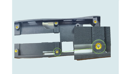
 Nylon parts printed using Selective Laser Sintering (SLS) or Multi Jet Fusion (MJF) processes can take advantage of standard-sized brass thermal-set inserts. Why brass? Brass is a soft metal with a low annealing temperature. Before installing the brass insert into the hole, heat it quickly with a soldering iron. This will cause the nylon to deform, allowing it to flow and fill the voids around the insert, providing a tight grip around the insert upon cooling. Using brass thermal-set inserts in your designs also helps deliver durability. Should you need a thermal-set insert other than brass, you can also specify those made from aluminum or stainless steel.
For parts printed using the Stereolithography (SLA) process, the insert style is different. In this case, standard press-fit inserts are used. They do not require heat to set. Instead, these press-fit inserts are secured with an epoxy to provide strength and security.
Designing for Tapping and Inserts in Plastic 3D-Printed Parts
When determining the type and size of tap or inserts you will need, be sure to provide us with technical drawings that clearly indicate thread size, pitch, and depth requirement. When designing for heat-set inserts, be sure to follow the guidelines in the table below for best fit. While we can’t guarantee size of fit or depth of inserts, we do ensure they are flush with the surface of the part. In some cases, we have built custom jigs for certain customer requirements.
Design Requirements for Heat-Set and Press Fit Inserts:
Minimum Wall Thickness: 0.030 in. (0.762mm)
Minimum Distance to Adjacent Features: 0.250 in (6.35mm)
Maximum Height of Adjacent Features: 4.0 in. (101.6mm)
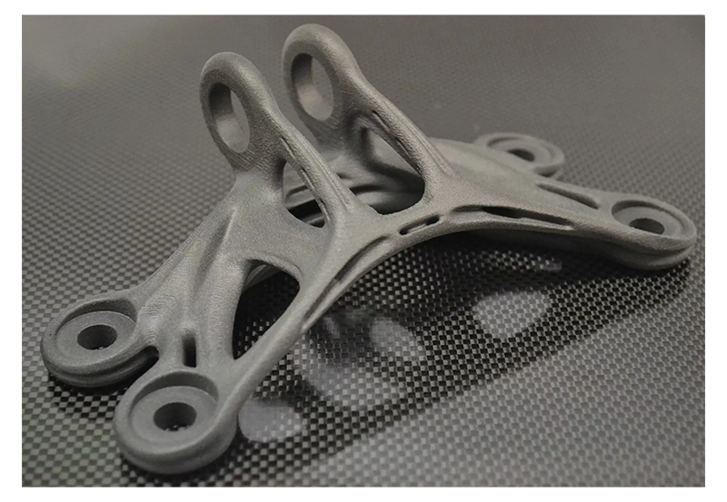
In metal 3D printed parts, you can choose between turning threads or tapping threads. Turned threads are threads that are cut into the surface of a part using a lathe or other machining equipment. This method produces more accurate and consistent threads, but typically requires longer machining times and higher costs.
Tapping threads involves using a tap or other tool to press threads into the surface of the part. This method is usually faster and cheaper, but the resulting threads may not be as precise or consistent as turned threads.
Which method you choose depends on the specific requirements of the part and your budget. If high precision threads are required, turning threads may be a better choice. If cost and time are major considerations, tapping threads may be a better choice.
It should be noted that tapping threads can be difficult in some materials such as Inconel 718 and cobalt chromium alloys because these materials are harder than the tap itself. In such cases, turning threads may be a better option. Tips on Designing for Tapping and Inserts in Metal 3D-Printed Parts
When requesting a quote for metal 3D-printed parts, it is essential to provide detailed thread information on the technical drawings. Our team can review any technical drawings that clearly specify the thread size, pitch, class of fit, and position requirement.
Special Request Inserts and More
The above information covers our standard processes for accommodating 3D printing customers. However, we welcome out-of-the-box design requests. You can send us the inserts you would like us to use, or we can order them for you, including larger inserts for bigger parts. We also offer assembly services for dowel pins. Please don’t hesitate to inquire about any specific requirements. Our applications engineers are here to assist you with lead time, cost analysis, and design objectives when it comes to threading and inserts in 3D-printed parts.

