


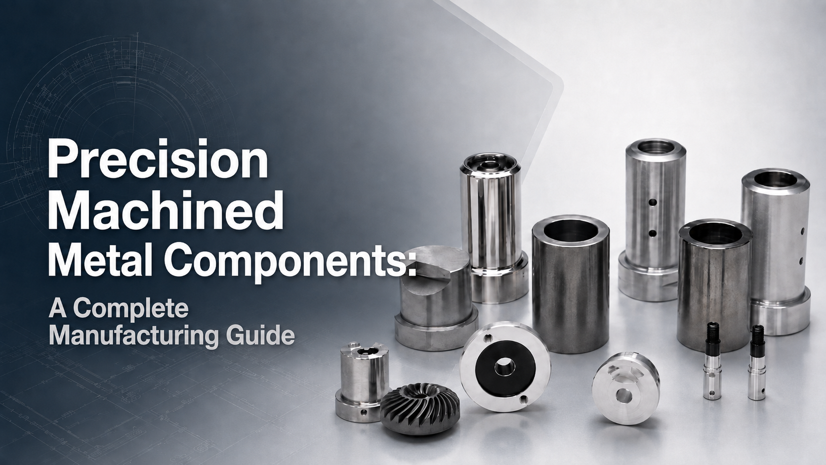
"Präzisionsgefertigte Metallkomponenten" deckt eine enorme Bandbreite an Teilen ab – ein chirurgisches Titaninstrument, ein optischer Linsenlauf aus Aluminium, ein Sensorgehäuse aus Edelstahl und ein druckgegossenes Telekommunikationsgehäuse sind alles Präzisionsmetallkomponenten, doch jede erfordert einen anderen Prozess, eine andere Materialstrategie und einen anderen Prüfansatz. Der Begriff beschreibt ein Anforderungsniveau, nicht eine einzelne Fertigungsmethode.
Diese Breite macht die Beschaffung so schwierig. Ein Lieferant, der zum hochvolumigen Druckguss fähig ist, erreicht möglicherweise keine ±1 μm bei einer optischen Halterung; ein Betrieb, der sich durch komplexe 5-Achsen-Bearbeitung auszeichnet, verfügt möglicherweise nicht über die Prüfinfrastruktur, um GD&T-Angaben zu verifizieren. Das Verständnis, welcher Prozess, welches Material und welches Qualitätssystem tatsächlich zu Ihrem Teil passt, ist der Unterschied zwischen einem reibungslosen Produktionsanlauf und einer Reihe teurer Überarbeitungen.
Dieser Leitfaden bietet einen vollständigen Überblick über präzisionsgefertigte Metallkomponenten: die verfügbaren Fertigungsprozesse und wann jeder angewendet wird, wie die Materialauswahl die Bearbeitbarkeit und Kosten beeinflusst, realistische Toleranz- und Oberflächengütefähigkeiten, die Branchen, die diese Teile bedienen, und wie fertige Komponenten geprüft und verifiziert werden.

Was macht eine Komponente „präzisionsgefertigt“?
Es gibt keinen einzelnen Toleranzwert, der die Präzisionsbearbeitung definiert, aber in der Praxis ist die Schwelle dort, wo Standardwerkstatttoleranzen nicht mehr ausreichen. Allgemeine Bearbeitungstoleranzen von ±0,1 mm sind für Halterungen und Strukturteile ausreichend; Präzisionsarbeiten beginnen typischerweise bei ±0,02 mm und reichen bis zu ±1 μm für Ultrapräzisionsanwendungen wie optische Ausrichtungsmerkmale.
Was Präzisionsarbeiten tatsächlich unterscheidet, ist nicht nur die Zahl auf der Zeichnung – es ist alles, was erforderlich ist, um diese Zahl wiederholbar einzuhalten: Bezugsstrategie, Vorrichtungsdesign, thermische Kontrolle in der Maschinenumgebung, Werkzeugverschleißmanagement und eine Inspektion, die in der Lage ist, das Ergebnis zu verifizieren. Ein Teil ist präzisionsgefertigt, wenn das gesamte Produktionssystem darauf ausgelegt ist, eine Spezifikation einzuhalten, nicht wenn ein einzelnes Merkmal zufällig innerhalb der Toleranz liegt. Unser Artikel über wie die CNC-Fräspräzision in der realen Produktion aufrechterhalten wird beschreibt, wie diese Disziplin in der Werkstatt aussieht.
Fertigungsprozesse für Präzisionsmetallkomponenten
Unterschiedliche Geometrien und Volumina erfordern grundsätzlich unterschiedliche Prozesse. Die meisten Präzisionskomponenten verwenden einen primären Prozess, der oft durch einen sekundären Vorgang für Merkmale ergänzt wird, die der primäre Prozess nicht erzeugen kann.
| Prozess | Am besten geeignet für | Typisches Volumen |
|---|---|---|
| CNC-Fräsen | Prismatische Teile, Taschen, komplexe 3D-Oberflächen | Prototyp bis mittleres Volumen |
| CNC-Drehen | Zylindrische Teile, Wellen, Gewindebohrungen | Prototyp bis hohes Volumen |
| 5-Achsen-Bearbeitung | Komplexe Geometrie, die mehrere Ausrichtungen in einem einzigen Setup erfordert | Prototyp bis mittleres Volumen |
| Draht-EDM | Gehärtete Materialien, scharfe Innenkanten, schmale Schlitze | Geringes bis mittleres Volumen, selektive Merkmale |
| Druckguss | Aluminium-/Zink-/Magnesiumgehäuse in großen Mengen | 10.000+ Stück |
| Metallspritzguss (MIM) | Kleine komplexe Teile aus Stahllegierungen | Mittleres bis hohes Volumen |
Die Entscheidung zwischen Fräsen und Drehen wird in der Regel eher durch die Teilegeometrie als durch Präferenz bestimmt – unser Vergleich zwischen CNC-Fräsen und CNC-Drehen behandelt, wo jede Anwendung zum Tragen kommt. Für Komponenten mit Geometrien, die über die Standard-3-Achsen-Fähigkeit hinausgehen, reduzieren fortschrittliche CNC-Bearbeitungsansätze wie die simultane 5-Achsen-Bearbeitung die Einrichtungszeiten und die damit verbundenen kumulativen Fehler.
Wenn das Volumen den Punkt überschreitet, an dem die individuelle Bearbeitung jedes Teils wirtschaftlich sinnvoll ist, verschiebt sich der Vergleich zu Near-Net-Shape-Verfahren. CNC-Bearbeitung versus Metallspritzguss ist der relevante Vergleich für kleine komplexe Stahlteile, während Hochdruck-Aluminiumdruckguss für größere Nichteisen-Gehäuse gilt. Wenn Sie sich nicht sicher sind, welche Prozesskategorie überhaupt passt, führt unser Leitfaden zur Wahl des richtigen Prozesses für Präzisionsteile systematisch durch die Entscheidung.

Materialauswahl und ihre Auswirkungen auf die Bearbeitung
Die Materialwahl beeinflusst weit mehr als nur die mechanischen Eigenschaften des fertigen Teils – sie verändert erreichbare Toleranzen, Werkzeugverschleißraten, Zykluszeiten und Kosten, manchmal um ein Vielfaches.
| Material | Bearbeitbarkeit | Gängige Anwendungen |
|---|---|---|
| Aluminium 6061 / 7075 | Ausgezeichnet | Optikgehäuse, Gehäuse, Halterungen |
| Edelstahl 303 / 304 / 316 | Mäßig | Medizinische Instrumente, korrosionsbeständige Hardware |
| Titan Ti-6Al-4V | Schwierig – geringe Wärmeleitfähigkeit, Kaltverfestigung | Medizinische Implantate, Luft- und Raumfahrtstrukturen |
| Messing / Bronze | Ausgezeichnet bis gut | Armaturen, Buchsen, Feingewindekomponenten |
| Technische Keramiken | Sehr schwierig – erfordert spezialisierte Werkzeuge | Verschleißflächen, isolierende Komponenten |
| Kohlefaserverbundwerkstoff | Spezialisiert – abrasiv, erfordert Staubkontrolle | Leichte Strukturkomponenten |
Titan veranschaulicht den Punkt gut: Seine schlechte Wärmeleitfähigkeit konzentriert die Wärme an der Schneide, anstatt sie in den Span abzuleiten, was den Werkzeugverschleiß erhöht und die Vorschubgeschwindigkeiten einschränkt. Unser detaillierter Leitfaden zur Präzisions-Titan-CNC-Bearbeitung behandelt die Strategien, die eingesetzt werden, um dies zu umgehen. Edelstahl stellt eine andere Herausforderung dar – die Kaltverfestigung bei unterbrochenen Schnitten –, die in unserem Leitfaden zur CNC-Bearbeitung von Edelstahl behandelt wird. Für einen breiteren Überblick über das verfügbare Materialsortiment sehen Sie sich die gesamte Palette der von uns bearbeiteten Materialien an.
Toleranzen und Oberflächengüte
Toleranz- und Oberflächengüteanforderungen sollten der Funktion folgen, nicht der Gewohnheit. Eine Überspezifikation treibt die Kosten in die Höhe, ohne die Leistung des Teils zu verbessern, und ist eine der häufigsten Ursachen für unnötige Ausgaben bei Präzisionskomponenten.
| Anforderungsniveau | Typische Toleranz | Typische Oberflächengüte |
|---|---|---|
| Standardbearbeitung | ±0,1 mm | Ra 3,2 μm |
| Präzisionsbearbeitung | ±0,02 mm | Ra 1,6 μm |
| Hochpräzision | ±0,005 mm | Ra 0,8 μm |
| Ultrapräzision / Optische Qualität | ±1 μm | Ra ≤ 0,1 μm |
Die Oberflächengüte verdient besondere Aufmerksamkeit, da sie die Funktion auf nicht immer offensichtliche Weise beeinflusst – Dichtungsverhalten, optisches Streulicht, Reibung an Passflächen und Beschichtungshaftung hängen alle davon ab. Unser Artikel über warum die Oberflächengüte bei Präzisionsteilen wichtig ist, behandelt, wie die Anforderungen an die Oberflächengüte spezifiziert werden sollten. Wo Korrosionsschutz oder Lichtabsorption bei Aluminiumkomponenten erforderlich ist, ist Schwarzanodisierung die gängigste Behandlung, obwohl dies dimensional berücksichtigt werden muss, da die Beschichtung Dicke hinzufügt.
Industrieanwendungen
Präzisionsgefertigte Komponenten dienen mehreren Branchen, jede mit spezifischen Anforderungen jenseits der Maßhaltigkeit:
Optik und Photonik – Linsenfassungen, Halterungen und Gehäuse, bei denen Ausrichtungstoleranzen die optische Leistung direkt bestimmen und interne Oberflächen Streulicht kontrollieren müssen.
Medizinprodukte – Instrumente und Implantatkomponenten, die biokompatible Materialien, Rückverfolgbarkeit und ISO 13485-konforme Prozesskontrolle erfordern.
Halbleiterausrüstung – Komponenten, die extreme Sauberkeit, Dimensionsstabilität und oft spezialisierte Materialhandhabung erfordern.
Robotik und Automatisierung – Struktur- und Gelenkkomponenten, die Gewicht und Steifigkeit ausbalancieren.
Wärmemanagement – Kühlplatten, Kühlkörper und Kühlgehäuse, bei denen Dichtungsintegrität und thermischer Kontakt ebenso wichtig sind wie Abmessungen.
Optische Komponenten stellen unsere tiefste Spezialisierung dar, die in unserem Leitfaden zu Präzisionsoptischen Baugruppen umfassend behandelt wird. Für medizinische Arbeiten, bei denen Dokumentation und Materialrückverfolgbarkeit ebenso wichtig sind wie die Bearbeitung selbst, siehe unseren Leitfaden zur CNC-Bearbeitung für medizinische Geräte.

Inspektion und Qualitätsprüfung
Eine Toleranz auf einer Zeichnung ist nur dann aussagekräftig, wenn eine Verifizierungsmethode existiert, die sie bestätigen kann. Einfache lineare Abmessungen können mit Messschiebern und Mikrometern überprüft werden, aber geometrische Anforderungen – Position, Konzentrizität, Ebenheit, Profil – erfordern eine Koordinatenmessung, die sich auf die Bezugsstruktur des Teils bezieht.
Hier wird die KMG-Inspektion notwendig und nicht optional. Ein KMG richtet das Teil an seinem spezifizierten Bezugskoordinatensystem aus und bewertet Merkmale als vollständige geometrische Entitäten, was die einzige Möglichkeit ist, GD&T-Angaben korrekt zu verifizieren. Bei der Überprüfung eines Inspektionsberichts eines Lieferanten ist es eine vernünftige Methode zu beurteilen, ob kritische Merkmale tatsächlich verifiziert wurden, wenn der Bericht eine definierte Bezugsstruktur referenziert – und nicht nur eine Liste isolierter Abmessungen.
Häufige Probleme und wie man sie vermeidet
Mehrere Probleme sind für einen überproportionalen Anteil der Präzisionsbearbeitungsprobleme verantwortlich:
Überspezifizierte Toleranzen. Das Anwenden enger Toleranzen auf nicht-funktionale Merkmale vervielfacht die Kosten, ohne die Leistung zu verbessern. Toleranzen sollten nur dort am engsten sein, wo es die Funktion erfordert.
Fehlende oder unklare Bezugsstruktur. Ohne klar definierte Bezugspunkte können ein Zerspaner und ein Inspektor dieselbe Zeichnung unterschiedlich interpretieren, was zu Teilen führt, die "innerhalb der Toleranz" gegen den falschen Bezug gemessen werden.
Dünnwandigkeit und Verformung. Dünne Abschnitte können sich unter Schnittkräften oder Klemmdruck verformen, wodurch Teile entstehen, die in der Vorrichtung korrekt, aber nach dem Lösen nicht mehr stimmen.
Oberflächenbehandlung nicht dimensional berücksichtigt. Eloxieren und Plattieren fügen Dicke hinzu, was bei eng sitzenden Bohrungen und Gewindemerkmalen von Bedeutung ist.
Unsere Aufschlüsselung von 23 häufigen CNC-Bearbeitungsproblemen und praktischen Lösungen behandelt diese und andere Probleme im Detail.
Die Präzisionsfertigungskapazität von XY-Global
Bei XY-Global werden präzisionsgefertigte Metallkomponenten nach ISO 9001 und ISO 13485 zertifizierten Prozessen hergestellt, mit einer Bearbeitungsgenauigkeit von ±1 μm und Oberflächengüten von Ra ≤ 0,1 μm, wo es die Anwendung erfordert. Unsere Fähigkeiten umfassen CNC-Fräsen und -Drehen, 5-Achsen-Bearbeitung, Draht- und Senkerodieren, Druckguss, Feinguss und MIM – was bedeutet, dass die Prozessauswahl dem tatsächlichen Bedarf Ihres Teils folgen kann, anstatt dem, was ein Ein-Prozess-Lieferant zufällig anbietet.
Die Produktion kann innerhalb eines Tages nach Auftragsbestätigung beginnen, und kostenlose Prototypenunterstützung ermöglicht es, ausrichtungskritische oder toleranzempfindliche Designs vor der Verpflichtung zu einem Volumen zu validieren. Jedes Projekt beinhaltet vor Produktionsbeginn eine DFM-Überprüfung, und eine KMG-Inspektion verifiziert GD&T-kritische Merkmale anhand Ihrer spezifizierten Bezugsstruktur. Unser Ingenieurteam kann Ihre Zeichnung überprüfen und den Prozess, das Material und den Inspektionsansatz empfehlen, der für Ihre Anwendung geeignet ist.
FAQ
Welche Toleranz sollte ich für eine präzisionsgefertigte Komponente angeben?
Geben Sie die lockerste Toleranz an, die das Teil noch funktionsfähig macht. Enge Toleranzen sollten selektiv auf Merkmale angewendet werden, die Passung, Ausrichtung oder Dichtung bestimmen, während nicht-funktionale Oberflächen Standardbearbeitungstoleranzen zu deutlich geringeren Kosten verwenden können.
Welches Material ist am besten für präzisionsgefertigte Teile?
Es hängt von der Funktion ab und nicht von einer universell besten Wahl. Aluminium bietet die beste Kombination aus Bearbeitbarkeit und Kosten für die meisten Gehäuse und Strukturkomponenten, Edelstahl, wenn Korrosionsbeständigkeit oder Festigkeit erforderlich ist, und Titan, wenn Festigkeit-zu-Gewicht oder Biokompatibilität die höheren Bearbeitungskosten rechtfertigt.
Was ist der Unterschied zwischen Präzisionsbearbeitung und Standard-CNC-Bearbeitung?
Die Standard-CNC-Bearbeitung hält typischerweise etwa ±0,1 mm, während die Präzisionsbearbeitung bei etwa ±0,02 mm beginnt und zusätzliche Kontrollen erfordert – Vorrichtungsdesign, Wärmemanagement, Werkzeugverschleißüberwachung und KMG-Inspektion –, um diese Toleranzen über eine Produktionsreihe wiederholbar einzuhalten.
Welche Informationen benötige ich für ein Angebot?
Eine 2D-Zeichnung mit Toleranzen und GD&T-Angaben, ein 3D-Modell, Materialspezifikation, Anforderungen an Oberflächengüte und -behandlung sowie die Menge. Das Notieren, welche Merkmale funktional kritisch sind, hilft, die Bearbeitungsstrategie und Inspektion dort zu konzentrieren, wo es wirklich darauf ankommt.

Aktie:
Feinguss vs. Druckguss: Materialien, Toleranzen und Anwendungsbereiche
Präzisionsteile für galvanometrische optische Scanner